
Why Gate Design Matters
You’ve just designed a fantastic part to be cast out of zinc: your tolerances all work out for castable features, you’ve included draft to help get the part out of the mold, and you even thought about which features will help you maximize your tool life. You’re all done and ready to issue a Purchase Order for tooling, right?
Unfortunately, you are not done yet: You still have to consider how you are going to channel the molten metal into the die to maximize the performance of your part. Thankfully, we are here to help. At Deco, we will take the lead in designing the features of the tool to get liquid metal from the pot, into the tool, and then into the part.
A poor die casting gate design can ruin an otherwise perfect casting. Gate runner sprue design has a direct impact on part quality, production cost, and tool life. Getting it right saves time, reduces scrap, improves tooling, and eliminates costly redesigns.
At Deco Products, we have the engineering expertise and the diecast experience to make the design process simple for you.
What are the Spure, Gate and Runner?
In high-pressure zinc diecasting, a plunger forces the molten metal from a revisor pot through the sprue, into the runner, through the gate, and into the empty cavity, which forms the part.
The sprue is the cone-shaped feature, where the metal starts its journey from the pot into the die.
The runner is the path the molten metal takes through the die to get from the sprue to the gate.
The gate is where the runner intersects with the part-cavity.
Designing the Gate
Gate design is crucial to the success of die casting. The gate controls how molten material enters the mold cavity: poor gate placement causes turbulence, trapped air, and surface defects, whereas proper design ensures smooth fill and consistent quality throughout production. The goal is to reduce turbulent flow and minimize air entrapment. This is difficult to accomplish as the metal is injected into the die very quickly, typically in 0.2 seconds.
Gate sizing requires careful balance. Larger gates improve material flow but may reduce surface finish. Small gates save material but can increase defects. Engineers balance these factors for each casting.
Often, the customer has restrictions on what they consider decorative surfaces. They will not want a gate location in a particular area. That adds complications with the geometry of the part. When we cannot place a gate where it needs to be, the part may require a machining operation.
For example, a secondary machining may be a buff operation to minimize the gate presence as much as possible. The gate location can play a part in the cost-effectiveness of the casting. Strategic and collaborative gate design is essential for designing a cost-optimized part.
Our Engineers can also select the type of gate based on your product needs. Whether you need a fan gate, edge gates, a tunnel gate, or any other type of gating system, you can trust our team to develop the sprue runner and gate that optimize the flow of molten metal into your part.
The Sprue and Runner System
The sprue and runner are also essential to design correctly. Design engineers must ensure the size and shape of this pathway correctly to maintains pressure and flow rate as metal flows into the cavity.
The sprue controls the entry of molten material into the die. The sprue bushing creates a seal between the machine nozzle and the die, thereby reducing pressure loss and improving the flow balance. As the metal flows from the sprue into the runner, metal is distributed throughout the cavity or cavities.

The design goal is to maintain consistent pressure and temperature throughout the fill-time. The engineers also want to ensure the molten zinc flows along the surfaces of the mold with as little turbulence as possible.
The design of the gate is also essential to balance the tradeoff between good flow into the part, and a runner that can be broken off easily. If the gate is too small, flow will be poor or turbulent. If the gate is too large, separate the part from the gate will be difficult, potentially leave burs, and also leave porosity or voids where the gate attached the part.
Overflow Design
Many times, we cannot design a great part that will fill well with a great runner and gate design alone. We may also need to include something called an “overflow”. An overflow is an extra feature designed to help the molten zinc flow properly into the part. Overflows are then removed from the part, much like the runner and sprue.
Overflows are typically used to draw air out of the casting as molten material fills the cavity. Without proper overflows, trapped gases create porosity and surface blisters, compromising part quality. Our Engineers use different overflow styles to prevent gases from reentering the casting. Part geometry and wall thickness influence the decision on where to place the overflow
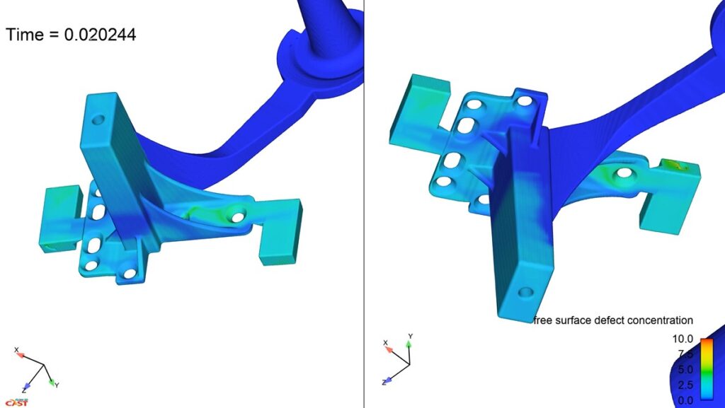
Simulation-Driven Gating Success
Poorly placed gates or missing overflows trap air within the casting. This leads to blisters and internal voids, which weaken the structural integrity. Rather than engage in costly trial-and-error design, our team utilizes flow simulation to verify the design concepts before we cut any tool steel.
This Flow simulation software lets us test radical designs with confidence. Jim Myers, Senior Engineer, recalls designing a complex table foot casting:
“I went with a bizarre gate, what we call caliber gates, where we have two tangential gates approaching each other,” Jim explained. “This is a radical concept: fill it in the center and have the flow keep building and push the air out,” Jim noted.
The simulation proved the design before tooling investment. This analysis provided confidence to build the production tool. The result was an excellent surface finish in the casting, despite the unconventional strategy of colliding flow fronts within the casting.
Degating: the Gate Removal Process
Degating is the process where we remove the finished part from the gate. Once we’ve cast the part, we remove the gate using a variety of methods.
Most commonly, we de-gate parts using a vibratory process. Many gates are designed to allow the part to break away from the gate with little force. Thus we are able to shake or tumble the parts so the break off the gate.
For larger parts, or parts that require higher levels of surface finish quality, we often use a trim process. The trim allows us to make a clean cut to remove the part from the gate and overflow.
While this process is slower than the vibratory process and requires additional investment in tooling, it allows for a very precise removal of excess material.
Once the part has been removed from the gating, the leftover material (the gate, runner, and sprue) can be remelted and recycled into a new part.
Work with Our Engineering Experts
The die-casting process is undeniably complex from start to finish. Thankfully, we have a wonderful team of engineers and technicians who can guide you through the process and serve as your technical resources. Our team will help you ensure your product design is manufacturable, optimized for cost, and then handle the complex process of designing how to flow material into your part based on the needs of your application.
Feel free to reach out to us anytime to ask for help on your next project.
If you found this article helpful, you may be interested in reading more about die-cast design here: Understanding the Parting Line in Zinc Die Casting.
Our Design Team's Expertise

Michele Duwe
Michele Duwe is the Sales and Marketing Manager with Deco Products. She has eight plus years as a digital marketing manager and over a decade of sales and marketing experience.